Understanding how to implement VLANs on GS1910


It’s easy to implement VLANs on GS1910, Go to Configuration > VLANs
Please refer the table below
The default VLAN setting is shown in table 1-1

- Port VLAN: This field indicates the port belong to which VLAN, also this feature is the sameas the PVID.
- Ingress Acceptance: This field indicates the ingress rule.
2.1 Tagged and Untagged: This rule means that the switch received the packets which are tagged and untagged.
2.2 Tagged only: This rule means that the switch only received packet, which is tagged.
2.3 Untagged only: This rule means that the switch only received packet, which is untagged.
- Egress tagging: This field indicates the Egress rule.
3.1 Tagged all: This rule means that the packet is always tagged
3.2 Untagged all: This rule means that the packet is always untagged
3.3 Untagged port VLAN: This rule means that the packet will be untagged with the Port VLAN, but other VLANs will not be affected.
- Allowed VLANs: This field indicates that this port allows specific VLANs
Example1

Port 1 and 2, which is with PVID 10. Packets that are tagged and untagged will be received.
The Egress rule for Port 1 is “untag all” which means that all of the packet will be untagged.
The Egress rule for Port 2 is “tag all” which means that all of the packet will be tagged.
Both Port 1 and 2 allow VLAN 1,3,5-7 and forbid VLAN 2,4,8-10.
Setup the IP address for VLAN 10, Go to Configuration > System > IP
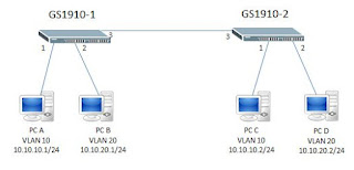
Scenario
PC A belongs to VLAN 10 on switch A, and PC B belongs to VLAN 20 on switch A
PC C belongs to VLAN 10 on switch B and PC D belong to vlan 20 on switch B
PCA is able to communicate with PC C but not PC B and D.
PCB is able to communicate to PC D, but not PC A and PC C
The topology is below;

Both GS1910 have the same configuration.

Verification
PC A ping PC C
c:\>ping 10.10.10.2
Pinging 10.10.10.2 with 32 bytes of data:
Reply from 10.10.10.2: bytes=32 time=1ms TTL=64
Reply from 10.10.10.2: bytes=32 time<1ms TTL=64
Reply from 10.10.10.2: bytes=32 time<1ms TTL=64
Reply from 10.10.10.2: bytes=32 time<1ms TTL=64
PC B ping PC D
PC B ping PC D
c:\>ping 10.10.20.2
Pinging 10.10.20.2 with 32 bytes of data:
Reply from 10.10.20.2: bytes=32 time=1ms TTL=64
Reply from 10.10.20.2: bytes=32 time<1ms TTL=64
Reply from 10.10.20.2: bytes=32 time<1ms TTL=64
Reply from 10.10.20.2: bytes=32 time<1ms TTL=64
To use the command “show mad address-table” to confirm that the MAC address is listed on the correct VLAN and port.
GS1910-1
GS1910-1# show mac address-table
Type VID MAC Address Ports
Dynamic 10 0c:4d:e9:a4:ed:a4 GigabitEthernet 1/3
Dynamic 10 d8:50:e6:11:05:93 GigabitEthernet 1/1
Dynamic 20 00:23:54:2e:98:b9 GigabitEthernet 1/3
Dynamic 20 fc:4d:d4:35:5a:d2 GigabitEthernet 1/2
GS1910-2
GS1910-2# show mac address-table
Type VID MAC Address Ports
Dynamic 10 0c:4d:e9:a4:ed:a4 GigabitEthernet 1/1
Dynamic 10 d8:50:e6:11:05:93 GigabitEthernet 1/3
Dynamic 20 00:23:54:2e:98:b9 GigabitEthernet 1/2
Dynamic 20 fc:4d:d4:35:5a:d2 GigabitEthernet 1/3
No comments:
Post a Comment